What is the process of standardizing adjustment work on CNC machines? Methodology for standardization of certain types of work Standardization of changeover on CNC machines
Calculation of time standards when processing parts on CNC machines Discipline: “Design of technological processes for modern multi-purpose machines” Completed by a student of group M 03 -721 -1 Pinegin S.N.
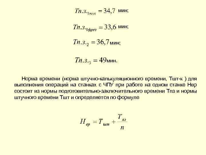
 Time standards are intended for technical standardization of work performed on universal and multi-purpose machines with numerical control. program controlled(CNC). The standard time (standard piece-calculation time, Tsht-k) for performing operations on CNC machines when working on one machine NVR consists of the standard preparatory-final time Tpz and the standard piece time Tsht and is determined by formula (1): , (1 ) where n is the number of parts in the launch batch.
 The rate of piece time is determined by formula (2): , (2) where Ttsa is the cycle time automatic operation machine according to program, min; , (3) where To is the main (technological) time for processing one part, min;
 , (4) where Li is the length of the path traversed by a tool or part in the feed direction when processing the i-th technological section (taking into account plunge-in and overtravel), mm; Smi – minute feed at a given technological section, mm/min; i =1, 2, …, n – number of technological processing sections; Тмв – machine auxiliary time (for supplying the tool part from starting points to processing and disposal areas; setting the tool to size, changing the tool, changing the magnitude and direction of feed, time of technological pauses, etc.), min;
 , (5) , (6) where L is the length of the path (or trajectory) traversed by the tool or part in the feed direction, mm; l 1, l 2, l 3 – length of approach, plunge and overtravel of the tool, respectively, mm. The value of L is determined based on the parameters of the part trajectory. Thus, when processing parts of a part with the tool moving along two coordinates, the length L is determined by the formula (7), (7)
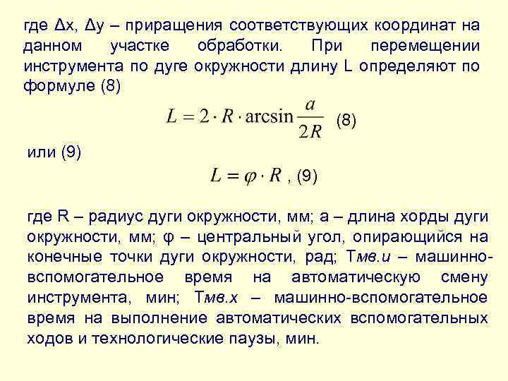 where Δх, Δу – increments of the corresponding coordinates in a given processing area. When moving the tool along a circular arc, the length L is determined by formula (8) or (9), (9) where R is the radius of the circular arc, mm; a is the length of the chord of the circular arc, mm; φ – central angle based on the end points of the circular arc, rad; Tmv. and – machine auxiliary time for automatic tool change, min; Tmv. x – machine-auxiliary time for performing automatic auxiliary moves and technological pauses, min.
 For machines with turret heads, the time is TMV. and can be determined by the formula (10), (10) where Type is the time of rotation of the turret head by one position, min; Кп – the number of positions by which it is necessary to rotate the turret to install the required tool; Typhoid – time of fixation of the turret head, min. For machines with contour control systems, the time is TMV. x can be determined by formula (11), (11)
 where Lxxj is the length of the path of the jth section of the automatic auxiliary move, mm; j=1, 2, …, t – number of sections of automatic auxiliary moves; Smu – rapid traverse minute feed. For machines with positional and universal (contour-positional) machine control systems, in which processing programming is carried out using standard cycles, analytically, time Tmv. x is difficult to determine due to the fact that specific machines, depending on their setup, have significant variations in the values of Sмхх and Lхх (associated with positioning settings). For a more accurate determination of the time TMB. x on these machines it is recommended to carry out preliminary timing in order to determine the actual time TMB. x when moving the table or tool a measured distance in the direction of different coordinates.
 In the case when standardization is carried out for an already designed technological process and there is a control program, time Tts. and is determined by direct timing of the part processing cycle. Auxiliary time for an operation is calculated using the formula (12), (12)
 where is TV. y – time for installing and removing the part manually or with a lift, min; TV op – auxiliary time associated with the operation (not included in the control program), min; TV meas – auxiliary non-overlapping time for measurements, min; Ktv - correction factor for the time of performing manual auxiliary work, depending on the batch of processed parts; ateh, aorg, aotl – time for technological and organizational maintenance of the workplace, for rest and personal needs during single-machine maintenance, percentage of operational time.
 Standards for auxiliary time for installation and removal of TV parts. They are given by type of fixture, regardless of the type of machine, and provide for the most common methods of installation, alignment and fastening of parts in universal and special clamping fixtures. The main factors influencing the installation and removal time of a part are the mass of the part, the method of installing and fastening the workpiece, the nature and accuracy of the alignment.
 Time standards for installing and removing parts provide for the following work: - when installing and removing manually: take and install the part, align and secure; turn the machine on and off; unfasten and remove the part, place it in a container; clean the device from shavings, wipe the base surfaces with a napkin; - when installing and removing with an overhead crane: call the crane; rig the part; transport the part to the machine; install the part, align and secure; turn the machine on and off; unpin part; call the tap; rig the part; remove from the machine and transport it to a storage location; rig the part; clean the devices or table surface from shavings, wipe the base surfaces with a napkin.
 When installing and removing a part with a lift at a machine (or group of machines), they perform the same work as when removing a part with an overhead crane, with the exception of calling the crane. When installed in special devices, auxiliary time is defined as the sum of time: for installation and removal of one part; for installation and removal of each subsequent part more than one in multi-place devices; to secure the part, taking into account the number of clamps; to clean the device from chips and wipe the base surfaces with a napkin. In the case of using robots, manipulators and satellite tables for installation and removal of parts, the auxiliary time is determined taking into account their design features.
 Standards for auxiliary time associated with the TV operation. op. . Auxiliary time associated with the operation, not included during the automatic operation cycle of the machine according to the program, provides for the following work: turn on and off the tape drive mechanism; set the specified relative position of the part and the tool along the X, Y, Z coordinates and, if necessary, make adjustments; open and close the cover of the tape drive mechanism, rewind and insert the tape into the reading device; advance the punched paper tape to its original position; check the arrival of the tool part at the specified point after processing; install the emulsion splash guard and remove it.
 Machine-auxiliary time associated with the transition, included in the program and related to the automatic auxiliary operation of the machine, provides for: supply of the tool part from the starting point to the processing zone and removal; setting the tool to the processing size; automatic tool change; feed switching on; idling when switching from processing one surface to another; technological pauses provided for when there is a sudden change in the direction of feed, to check dimensions, inspect the tool and reinstall or re-fasten the part. The machine-auxiliary time associated with the transition is determined from the passport data of the machines and is included as constituent elements during the automatic operation of the machine.
 Standards for auxiliary time for control measurements of TV. change . The required dimensions of parts processed on numerically controlled machines are provided in an automatic processing cycle. In this regard, the time for control measurements (after completion of work according to the program) should be included in the standard piece time only if this is provided technological process and taking into account the necessary frequency of such measurements during operation, and only in cases where it cannot be covered by the cycle time of the automatic operation of the machine according to the program.
 Time standards for servicing a workplace. Time for workplace maintenance is given by type and size of equipment, taking into account single-machine and multi-machine maintenance as a percentage of operational time. Technological maintenance of the workplace involves performing next works: - changing a tool (or a block with a tool) due to its dullness; - adjustment and adjustment of the machine during operation (changing the tool correction value); - sweeping and periodic cleaning of chips during work (except for sweeping chips from the base surfaces of installation devices, the time for which is taken into account in the auxiliary time for installing and removing the part).
 Organizational maintenance of the workplace includes work to care for the main and auxiliary equipment, technological and organizational equipment, containers related to the work shift as a whole: - inspection and testing of equipment during work; - laying out tools at the beginning and cleaning them at the end of the shift; - lubrication and cleaning of the machine during the shift; - cleaning the machine and workplace at the end of the shift.
 Time standards for rest and personal needs. Time for rest and personal needs for the conditions of servicing one machine by one worker is not separately allocated and is taken into account in the time for servicing the workplace. For multi-machine maintenance, time for breaks for rest and personal needs is provided, depending on the characteristics of the work.
 Standards for preparatory and final time. The standard time for setting up a machine is presented as the time for preparatory and final work to process a batch of identical parts, regardless of the batch, and is determined by the formula (13), (13) where Тпз is the standard time for setting up and tuning the machine, min; Тпз 1 – standard time for organizational preparation, min; Тпз 2 – standard time for setting up a machine, device, tool, software devices, min; Etc. arr – time standard for trial processing.
 The time for preparatory and final work is set depending on the type and size of the equipment, as well as taking into account the features of the program control system. The scope of work on organizational preparation is common to all CNC machines, regardless of their group and model. The time for organizational preparation includes: - receiving an order, drawing, technological documentation, software, cutting, auxiliary and control tools, fixtures, blanks before the start and handing them over after finishing the processing of a batch of parts at the workplace or in the tool storeroom; - familiarization with the work, drawing, technological documentation, inspection of the workpiece; - instructions from the master.
 In a brigade form of labor organization, when workpieces are transferred between shifts, organizational preparation takes into account only the time for familiarization with the work, drawing, technological documentation, inspection of workpieces and instructing the foreman. The work on setting up the machine, tools and devices includes adjustment work methods, depending on the purpose of the machine and design features: installation and removal of fastening devices; installation and removal of a block or individual cutting tools; setting the initial operating modes of the machine; installing the software into the reading device and removing it; zero position adjustment, etc.
 The time for trial processing of parts on machines of the turning and turret groups includes the time spent on processing the part according to the program and auxiliary time for performing additional techniques associated with measuring the part, calculating correction, entering correction values into the CNC system, and auxiliary time for techniques for controlling the machine and CNC system. The time for trial processing of parts on machines of rotary, milling, boring groups, multi-tasking machines includes time spent on processing parts using the test chip method and auxiliary time for performing additional techniques related to measuring the part, calculating the correction value, entering correction values into the CNC system, and auxiliary time for techniques for controlling the machine and the CNC system.
 To calculate the main time, it is necessary to determine the cutting modes for processing each surface of the part. They are determined according to general machine-building standards: - General machine-building standards for time and cutting modes for rationing work performed on universal and multi-purpose machines with numerical control. Part 2 – Standards for cutting conditions. – M.: Economics, 1990. - Metal cutting modes: reference book / Ed. Yu. V. Baranovsky. – 3rd ed. , processed and additional – M.: Mechanical Engineering, 1972. – 407 p. - Handbook of mechanical engineering technologist. In 2 vols. T. 2 / Pod. ed. A. G. Kosilova and others - 5th ed. , rev. – M.: Mechanical Engineering, 2003. – 944 p. , ill.
 An example of calculating time standards To calculate time standards, we present the initial data: drawing of the “Roller” part, workpiece material steel 45 GOST 1050-88, batch of parts 100 pcs, workpiece – round rolled steel with a diameter of 125 x 54. We will carry out the calculation in three cases: 1. 1) Processing on two CNC machines - a lathe (16 K 20 F 3) and a milling machine (6 R 13 RF 3). On lathe Two necks with a diameter of 30 h 12 are processed with CNC with trimming of the ends. The operation involves reinstalling the workpiece in a self-centering chuck with a pneumatic clamp. On a CNC milling machine, a 4 x 10 groove and 4 holes with a diameter of 16 mm are processed in a self-centering prismatic vice with a pneumatic clamp. 2) Machining on a 5-axis turning machining center. Processing takes place in a self-centering chuck with a pneumatic clamp in one operation with reinstallation of the workpiece. The same transitions are performed as on conventional CNC machines - turning, milling and drilling.

 3) Machining on a machining center with a sub-spindle. Processing takes place in a self-centering chuck with a pneumatic clamp in one operation with reinstallation of the workpiece. Such OCs have two chucks with pneumatic clamping and two tool heads. The role of the second chuck is played by the counter spindle, which reinstalls the workpiece and in which further processing of the workpiece takes place. The workpiece processing cycle is as follows: the workpiece is installed and secured in the chuck; they turn a neck with a diameter of 30 h 12 with trimming the end; The tool is automatically changed by turning the turret; drilling 4 holes with a diameter of 16 mm; the first turret goes back to the starting point; the counter spindle turns on and is automatically brought to the chuck, which continues to rotate at a given frequency; the counter spindle accelerates to the chuck rotation speed and automatically clamps the workpiece; the chuck automatically opens its jaws and the counter-spindle with the workpiece moves to its specified starting point; the second turret head is brought in and turns the neck with a diameter of 30 h 12 with trimming the end; automatic tool change and milling of a 4 x 10 groove is carried out; withdrawal of the turret to the starting point and switching off of the counter-spindle.
 Main time To The main time for all three cases is calculated according to general machine-building standards and taken as a constant value, i.e. To = const. The main time for turning, milling and drilling operations can be found from tables and empirical dependencies. The main time is determined by the formula. As a result, we get: min; min.
 Тмв – machine-auxiliary time (for supplying the tool part from the starting points to the processing zones and removal; changing the tool), min. We determine it based on machine data sheets and processing technology. min; min. Ttsa – cycle time of automatic operation of the machine according to the program, min. We determine min by the formula;
 ateh, aorg, aotl – time for technological and organizational maintenance of the workplace, for rest and personal needs during single-machine maintenance, percentage of operational time. For CNC and OC machines, this value is 14% of the operating time.
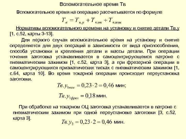 Auxiliary time TV Auxiliary time for an operation is calculated using the formula Standards for auxiliary time for installation and removal of part TV. y . For the first case, the auxiliary time for installation and removal is determined for two operations depending on the type of device, the method of installation and fastening of the part and the weight of the part. During the turning operation, the workpiece is mounted in a self-centering chuck with a pneumatic clamp, and during the milling operation, in a self-centering prismatic vice with a pneumatic clamp. During the turning operation, the workpiece is repositioned. min; min. When processing on a turning center, the workpiece is installed in a chuck with a pneumatic clamp with one reinstallation of the workpiece. min.
 When processing on an OC with a counter spindle, the workpiece is installed in a chuck with pneumatic clamping with one reinstallation of the workpiece using automatic installation of the workpiece in the counter spindle. min. Standards for auxiliary time associated with the TV operation. op. . min; min. Standards for auxiliary time for control measurements of TV. change . In all 3 cases it is equal to 0. The time for control measurements (after completion of work according to the program) should be included in the standard piece time only if this is provided for by the technological process and taking into account the necessary frequency of such measurements during the work process, and only in those cases , when it cannot be covered by the cycle time of the automatic operation of the machine according to the program.

 Auxiliary time TV min; min. Ktv - correction factor for the time of performing manual auxiliary work, depending on the batch of parts being processed.
 The norm of piece time is determined by the formula min; min. Standards for preparatory and final time. where Тпз – standard time for setting up and setting up the machine, min; Тпз 1 – standard time for organizational preparation, min; Тпз 2 – standard time for setting up a machine, device, tool, software devices, min; Etc. arr – time standard for trial processing.
 min; min. The standard time (standard piece-calculation time, Tsht-k) for performing operations on CNC machines when working on one machine NVR consists of the standard preparatory-final time Tpz and the standard piece time Tsht and is determined by the formula


page 1

page 2

page 3

page 4

page 5

page 6

page 7

page 8

page 9

page 10

page 11

page 12

page 13

page 14

page 15

page 16

page 17

page 18

page 19

page 20

page 21

page 22

page 23

page 24

page 25

page 26

page 27

page 28

page 29

page 30
CENTRAL BUREAU OF LABOR STANDARDS OF THE USSR STATE COMMITTEE FOR LABOR AND SOCIAL ISSUES
GENERAL ENGINEERING STANDARDS FOR TIME AND CUTTING MODES for standardizing work performed on universal and multi-purpose machines with numerical control
TIME STANDARDS
MOSCOW ECONOMY 1990
Standards for cutting time and modes were approved by a resolution of the USSR State Committee for Labor and social issues and the Secretariat of the All-Union Central Council of Trade Unions dated February 3, 1988 N9 54/3-72 and are recommended for use in machine-building enterprises.
Validity of the standards until 1994.
With the introduction of this collection, the General Machine-Building Standards for time and cutting modes for work performed on metal-cutting machines with program control (MGNII Labor, 1980) are cancelled.
Standards for time and cutting modes (4.1 and L) were developed by the Central Bureau of Labor Standards, Chelyabinsk Polytechnic Institute named after. Lenin Komsomol, Ryazan and Minsk branches of the Orgstakkinprom Institute with the participation of regulatory research organizations and mechanical engineering enterprises.
The first part contains standards for auxiliary time for installation and removal of parts associated with the operation; for control measurements; for workplace maintenance; breaks for rest and personal needs; time standards for setting up equipment; to adjust the tool outside the machine; methodology for calculating service standards, time and production standards for multi-machine maintenance.
The second part contains standards for cutting modes and all data on calculating the main time and machine-auxiliary time, i.e. to calculate the cycle time of automatic operation of the machine according to the program.
Time standards and cutting modes have been developed to calculate time standards for work performed on the most common types of universal and multi-purpose computer numerical control (CNC) equipment used in mechanical engineering in medium-scale and small-scale production.
Standards for time and cutting modes cover the work of machine tool setters and manipulators with program control, operators of machine tools with program control, and toolmakers.
The publication is intended for standardization specialists and technologists, as well as other engineering and technical workers involved in the development of control programs and the calculation of technically sound standards for maintenance, time and output for CNC machines.
At the end of the collection there is a review form, which is filled out by the organization and sent to CENT. 109028, Moscow, st. Solyanka, 3, building 3.
Providing cross-industry regulatory and teaching materials for labor is carried out at the request of enterprises and organizations through the local bookselling network. Information about these publications is published in the Annotated thematic plans for the publication of literature of the Economics publishing house and Book Trade Bulletins.
011(01) -90 ISBN 5 - 282 - 00697 - 9
KB - 32 - 76 - 89
© Central Bureau of Labor Standards of the USSR State Committee for Labor and Social Issues (CBNT), 1990
The piece time for assembly, adjustment and disassembly of the kit ipprumepm n.i d>* teleoperation is determined by the formula
^"Un* = S^shlr1 G ^"|i pr 2 * ^N1I|zh)* (1*1 M
where T shlzh - piece time for assembly, adjustment and disassembly of a set of tools for a detail operation, min; n - number of customizable ingtrumsn mu per distal operation, pcs.; T t ... T sh>fa - piece time for assembly, adjustment and ra:*Сх>рк different types tool included in the kit, min.
1.8. Tariffication of work should be carried out according to the Unified Tariff and Qualification Directory of Work and Professions of Workers (issue 2, approved by the Decree of the USSR State Committee on Labor and Social Issues and the All-Russian Central Council of Trade Unions of January 16, 1985 No. 17/2-541, taking into account subsequent additions and changes to it The discrepancy between the worker’s qualifications and the established level of work cannot serve as a basis for any changes in the time standards calculated according to the collection.
1.9. With the improvement of CNC machines and control systems, as well as in those cases, the cost in enterprises has already been achieved higher)! labor productivity with high-quality performance of work, reducing correction factors can be established to time standards.
In cases where the local time standards in force at enterprises are less than those calculated according to the standards, the current standards must be left unchanged.
1.10. Time standards are put into effect in the manner prescribed by the “Regulations on the organization of labor standardization in the national economy”, approved by Resolution of the USSR State Committee for Labor and Social Issues and the Presidium of the All-Union Central Council of Trade Unions dated June 19, 1986 No. 226/II-6.
L11. To explain the procedure for using time standards, examples of calculating preparatory-final time and piece time for setting up a tool are given below.
Examples of calculating time standards, cutting modes and the time of automatic operation of the machine according to the program are given in Part II of the collection in the relevant sections.
1.12. Examples of calculating standards for preparatory and final time and piece time for setting up a tool
1.12.1. Examples of calculating the norms of preparatory and final time
Initial data
1. The name of the operation is turning-turret.
2. Machine - CNC turret lathe.
3. Machine model - 1P426DFZ (diameter of the processed rod - 65 mm).
4. Model of the CNC device - "Electronics NTs-ZG, program carrier - memory.
5. Part name - amplifier piston.
6. Processed material - steel 45, weight - 0.5 kg.
7. The method of installing the part is in a collet chuck.
8. Working conditions: centralized delivery to workplace blanks, tools, fixtures, documentation and their delivery after processing a batch of parts; receiving instructions before starting to process the part. Group processing of parts is carried out (the collet chuck is not installed on the machine spindle).
The part processing program is compiled by a software engineer and entered into the memory of the CNC system by the lathe operator; the program contains 17 processed sizes.
9. Number of tools in setup - 5:
1. Cutter 2120-4007 T15K6 (groove).
2. Cutter 2102-0009 (through persistent).
3. Special cutter (groove).
4. Cutter 2130-0153 T15K6 (cutting).
5. Drill 2301-0028 (hole 010).
|
||||||||||||||||||||||||||||||||||||
|
Trial processing 6 The part is accurate (has surfaces with tolerances for diameters greater than the 11th qualifier, groove) for four tools and four measured Map 29, 8.8 according to the diameter of the surfaces (two outer surfaces: pos. 27, 0 50.3 MO and O 203 MO; one groove b = 6; ind. G; approx. single groove-undercut 0 30 parts 2, 3 |
||||||||||||||||||||||||||||||||||||
Map 29, 8.8+t
note 1
Total preparatory and final time for a batch of parts
1. The name of the operation is turning and rotary.
4. Device model CNC-N55-2, program carrier - punched tape.
5. Part name - flange. "l.
6. Processed material - ~ SCh20 cast iron, weight -1500 kg.
7. The method of installing the part is in four cams with boxes, each is secured with six bolts on the faceplate of the machine.
8. Working conditions: delivery of tools, devices, documentation, workpieces to the workplace and their delivery after finishing processing of a batch of parts is carried out by the operator (adjuster).
The tool on the device for setting outside the machine is not pre-set.
9. Number of tools in the setup - 4 (including one groove cutter, tools 1 and 2 - from the previous setup):
1. Cutter 2102-0031VK8 (through).
2. Cutter 2141-0059 VK8 (boring).
3. Cutter 2140-0048 VK8 (boring).
4. Cutter NZh212-5043 (groove).
|
||||||||||||||||||||||||||||||||||||||||||||
|
||||||||
|
Trial* treatment The part is precise (has surfaces with tolerances for diameters greater than the 11th grade, a groove) boring of grooves - one tool, one groove (08ООН9Х07ОО) boring and turning of external and internal surfaces - three tools, three surfaces variable in diameter - 0 1150h9.0 800N9, Card 30, pos. 49, ind. a Card 30, pos. 5, inl. in, all Map 30, note 1 25,5 0,85 - 21,7 263 |
||||||||
I t o g o T
Total preparatory time for a batch of parts
T„-T i1 + T„ a + T yarv ^ 91.9
Initial data
1. Name of the operation - turning.
Z Machine - chuck lathe with CNC.
3. Machine model - 1P756DFZ (the largest diameter of the product installed above the bed is 630 mm).
4. CNC device model - 2S85, program carrier - punched tape, memory.
5. Part name - flange.
6. The material being processed is SCh25 cast iron, weight - 90 kg.
7. The method of installing the part is in a three-jaw chuck.
8. Labor organization conditions: delivery*/to the workplace of tools, fixtures, documentation, workpieces and their delivery after processing a batch of parts is carried out by the operator (adjuster). Group processing of parts is carried out (a jaw chuck is not installed on the machine spindle).
The part processing program is compiled by a software engineer and entered into the memory of the CNC system by the lathe operator. The program contains 20 processed sizes.
adjustments):
1. Cutter 2102-0005 (through persistent).
2. Cutter 2141-0604 (boring).
3. Cutter 2141-0611 (boring).
4. Cutter NZh 2126-5043 (groove).
5 Number of tools in setup - 4 (tools 1 and 2 - from previous
Map, police, index
Time, mii
*1.0
1 Organizational preparation
Map 21. to 1). 2,3,4, inl. P
tions and their delivery after processing a batch of parts; receiving instructions before starting to process parts; Tool assembly is carried out in a special tool setting area for CNC machines.
9. Number of tools in setup - 25 (four tools: 1.12, 24.25 - from the previous setup):
1. End mill 6221-106.005 (plane 800x800).
2. Semi-finish cutter (hole 0 259.0).
3. Finishing cutter (hole 0259DN9).
4. Semi-finish cutter (hole 0169.0).
5. Finishing cutter (hole 0169.5Н9).
6. Rough cutter (hole 0 89).
7. Semi-finish cutter (hole 0 89.5).
8. Finishing cutter (hole 0 90js6).
9. Rough cutter (hole 0 79).
10. Semi-finish cutter (hole 0 79.5).
1L Finishing cutter (hole 0 80js6).
12. Disc cutter 2215-0001VK8 (lowering 0 205).
13. Rough cutter (hole 0 99).
14. Semi-finish cutter (hole 0 99.5).
15. Finishing cutter (hole 0100js6).
16. Semi-finish cutter (undercut 0130).
17. Drill 23004)200 (hole 0 8.6).
18. Tap 26804Yu03 (thread K1/8").
19. Drill 2301-0046 (hole 014).
20. Drill 2301-0050 (hole 015).
21. Countersink 2320-2373 No. 1VK8 (hole 015.5).
22. Reamer 2363-0050Н9 (hole 015.95Н9).
23. Reamer 2363-00550Н7 (hole 016Н7).
24. Drill 2317-0006 (centering).
25. Drill 2301-0061 (chamfer).
|
Hag, position, index |
Time, min |
||
|
Organizational preparation Total T P11 |
Card 25, pos. 1,3,4, ind. b |
4,0 + 2,0 + 2,0 8,0 |
|
|
Setting up the machine* devices, tools, software devices: | |||
|
install the device and shine |
Card 25, pos. 13 | ||
|
move the table, headstock and area convenient for adjustment |
Card 25, pos. 20 | ||
|
set the initial operating modes of the machine (spindle speed) |
Card 25, pos. 21 | ||
|
install tool blocks in the magazine and remove 21 tools |
Card 25, pos. 22 | ||
|
install the software into the reading device and remove |
Map 25, x 24 | ||
|
check the functionality of the reader and punched tape |
Card 25, x 25 | ||
|
set the initial X and Y coordinates (adjust the zero position) along the cylindrical surface |
Map 25, x 29 | ||
|
set the tool to the cutting length (Z axis for six tools: 1,7,12,16,24 and 25) |
Map 25, x 30 | ||
|
Total T„ 2 | |||
|
And |» O l O L F S II and s |
||||||||||||||||||||||||||||||||||||
|
||||||||||||||||||||||||||||||||||||
|
B Trial offset work The part is accurate (has surfaces with tolerances for lmams* t *ry above the I-th quality, groove) for four tools and three measured by dipmsh ru K;irta 2.4, 8.9 surfaces - e>*2c0hl0,<3 200Е17и канавка b = 10 тч. 6, чпл г Total T p lb Ka r."2K, b.V + 1 SHSHSH'CH.<ииС 1.1 |
||||||||||||||||||||||||||||||||||||
Total preparation time^extreme time for a batch of parts
T "1 + T "2 + T arr.
Example 5 Initial data
1. Name of the operation - vertical milling.
2. Machine - vertical milling with CNC.
3. Machine model - 6Р13РФЗ (with table length -1600 mm).
4. CNC device model - NZZ-1M; program carrier - punched tape.
5. Part name - strip.
6. Processed material - steel 45, weight -10 kg.
7. The method of installing the part is in a reconfigurable universal assembly device (USF).
8. Labor organization conditions: centralized delivery of workpieces, tools, devices, documentation to the workplace and their delivery after processing a batch of parts; receiving instructions before starting to process parts.
9. Number of tools in setup - 6 (tools 1 and 5 - from the previous setup):
1. Drill 2317-003 (centering).
2. Drill 22-2 (hole 0
3. Special end mill (for groove b = 20).
4. Milling cutter 2234-0007 (for groove b = 8Н9).
5. Drill 6-1 (hole 0 6).
6. Countersink 2350-0106 VK6 (lowering 016).
|
||||||||||||||||||||||||||||||||||||||||||||||||||||||||||||||||||||||||||||
|
Trial processing Milling the groove L, AN9 and L groove * 634 Card 33, 192 |
||||||||||||||||||||||||||||||||||||||||||||||||||||||||||||||||||||||||||||
Total T about 60 _
Total preparation and closing time for a batch of parts
Toz 1 + T and # 2 + Tprobr
1.12.2. An example of calculating the unit time for setting up a tool
Initial data
1. Name of the operation - assembly, adjustment and disassembly of a set of tools necessary for processing parts on a drilling-milling-boring machine.
2. Name of the device - BV-2027, with digital display.
3. Characteristics of the machine - cone 7:24 No. 50.
4. Labor organization conditions: delivery of tools and technical documentation to the toolmaker’s workplace is carried out by service production workers, dismantling of used tools is carried out by a toolmaker.
|
Piece time, mii | |||||
|
Tool used |
Map, position, index |
kya us-groyku and gathering* ku |
for disassembly | ||
|
Drill 0 83, drill chuck, sleeve |
type of connection - 1 |
2,64 ■ 0,45 - 1,19 | |||
|
2 M10 marks, adjustable thread-cutting chuck, holder |
type of connection - 2 |
3,15 * 0,65 = 2,05 | |||
|
3 Spade drill 0 32, mandrel, sleeve |
type of connection - 1 | ||||
|
4 Cutter mandrel adjustable for Map 38, oblique fastening, cutting, holder type of connection - 3, 0 boring hole - 80 mm | |||||
2. MULTI-SITE SERVICE
2.1. To develop and improve the efficiency of multi-machine maintenance of machine tools with numerical control (CNC), the enterprise must create certain organizational and technical conditions that can significantly increase the productivity of operators and adjusters. Work on servicing CNC machines involves combining the functions of an operator and an adjuster.
2.2. The most economically feasible form of labor organization in areas of CNC machine tools is link (group). In the link (group) form, a certain service area is assigned to a link or group of workers included in the team.
The experience of enterprises testifies to the advantage of the link form of labor organization when servicing CNC machines, which ensures better use of working time and equipment.
The best division of labor when servicing workplaces of CNC machines is considered to be one in which the multi-machine operator and the setup operator have, in addition to the separated ones, some common functions. General functions include carrying out operational work, adjusting machines; The functions of setting up equipment are carried out by an adjuster. This division of labor has economic and social advantages. The ability to perform the same functions by two workers allows you to reduce equipment downtime due to the coincidence of the need to service several machines and improve the use of working time. At the same time, the mastery of adjustment functions by multi-machine operators increases the content of their work and creates opportunities for growth in qualifications.
2.3. To introduce multi-machine maintenance and rational use of working time, it is necessary to create a sufficient scope of work for each worker. Equipment and organizational supplies must be conveniently located and meet the requirements of the brigade form of labor organization. For this purpose, the design of the organization of workplaces for multi-machine operators is carried out in accordance with the diagrams presented in Section 3.5. Preference should be given to schemes that ensure full worker load with active work, the shortest length of transitions within the workplace and good visibility of all machines.
There are cyclic and non-cyclic maintenance of machines at a multi-machine workplace. During cyclic maintenance, the worker consistently performs auxiliary work techniques, moving from machine to machine. During non-cyclic maintenance, the worker approaches the machine on which automatic operation has ended, regardless of the location of the machines on the site.
2.4. Calculation of service standards
2.4.1. Service standards are set taking into account the normal level of employment - K yes. When working on CNC machines, taking into account heterogeneous technological operations with a changing range of manufactured parts, K l l - 0.75...0.85. When working on backup machines K A5 = 0.85. D95.
Z42. Calculation of the number of machines served by one worker, required to service the CNC equipment available on the site, and the number of units is carried out using the formulas:
a) when working on backup machines
П с = (-bs- + 1) К Л1; (21)
b) when working on machines that produce heterogeneous products,
"c = + 1) k, (2-2)
where is the cycle time of the automatic operation of the machine (machine-programmed time for processing a part, the operation of a manipulator or robot, not covered by the processing time of the part), min (according to formula 13); 2j - sum of processing time
rolls of parts (according to the program and operation of the manipulator or robot) at the workplace for the period of one cycle, min; T, is the time a worker is busy performing manual, machine-manual work, active monitoring of the progress of the technological process, etc., min; Jj T a - the sum of the worker’s employment time on all serviced machines for the period of one cycle, min; - normal level of employment.
The number of units is calculated using the formula
S - -b»-, (23)
where S is the number of units required to service the equipment available on site, people; Pu Ch - the number of CNC machines installed on the site; p s - the number of machines serviced by one worker.
T, - T, y + TYo, + T MM(+ T. + T n + T^, (2.4)
where T lu is the time for installing and removing the part manually or with a lift, min; Тіо„ - auxiliary time associated with the operation (not included in the control program), min; T i - time of active monitoring of the technological process, min; T p - time of transition of a multi-machine operator from one machine to another (during one cycle), min (given in Table 2.4); T m - auxiliary time for control measurements, min; - time for servicing the workplace, min.
2.43. The number of machines at multi-machine workplaces is determined on the basis of a comparative calculation of labor productivity and processing costs, especially when installing expensive equipment such as multi-purpose CNC machines.
The cost-effective number of machines serviced by a multi-machine operator can be determined by comparing the costs associated with the operation of a multi-machine operator and equipment when operating the machines and various options for the equipment being serviced.
When calculating the number of serviced machines corresponding to the lowest total costs of performing operations, take into account the costs of performing operations, the costs of materialized labor required to produce the same volume of products, which include depreciation costs, expenses for routine repairs and maintenance, electricity, through 0
ratio and employment coefficient K/. 3
1. GENERAL PART
1.1. Standards for time and cutting modes are intended for technical regulation of work performed on universal and multi-purpose machines. numerical program control in conditions of small-scale and medium-scale production types. One of the main characteristics of the type of production is the coefficient of consolidation of operations (K^), calculated by the formula
where O is the number of different operations; P is the number of jobs performing various operations.
The coefficient of consolidation of operations in accordance with GOST 3.1121-84 is taken equal to:
10 < К м £ 20 - для среднесерийного типа производства;
20 < 3 40 - для мелкосерийного типа производства.
The value of the operation consolidation coefficient is taken for a planning period equal to one month.
The collection is based on the medium-batch type of production. For small-scale production enterprises or for individual sections in a medium-scale production type operating in small-scale production conditions, correction factors for auxiliary time are applied.
1.2. When introducing a brigade (team, group) form of labor organization, standards can be used to calculate service standards, complex time standards, production and number standards.
13. The use of machine tools with numerical control is one of the main directions of automation of metal cutting, provides a significant economic effect and makes it possible to free up a large number of universal equipment, as well as improve the quality of products and working conditions of machine operators. The greatest economic effect from the introduction of numerical control machines is achieved when processing parts with a complex profile, which is associated with constantly changing cutting parameters (speed, feed direction, etc.).
The use of numerically controlled machines instead of universal equipment allows:
use multi-machine service and brigade (team, group) form of labor organization;
increase labor productivity by reducing auxiliary and machine processing time on the machine;
eliminate marking operations and interoperational control; thanks to abundant cooling and favorable conditions for chip formation, increase processing speed and eliminate the need for visual monitoring of markings;
automate auxiliary work techniques (approach and removal of a tool or part, setting a tool to size, changing a tool), use optimal tool trajectories;
Expenses* associated with one minute of work of the main worker-multi-machine operator based on the average percentage of compliance with standards, taking into account the accrual of wages, the cost of maintaining auxiliary and maintenance personnel -
Job category
w
2.4.4. Calculation of occupancy rate
t+t
still - operational time, min.
|
Table 2.2 Cost of operating CNC machines for one minute |
||||||||||||||||||||||||||||||||||||||||||||||||||||||||||||||||||||||||||||||||||||||||||||||||||||||||||||||||||||||||||||||||||||||||||||||||||||||||||||||||||||||||||||||||||||||||||||||||||||||||||||||||||||||||||||||||||||||||||||||
|
||||||||||||||||||||||||||||||||||||||||||||||||||||||||||||||||||||||||||||||||||||||||||||||||||||||||||||||||||||||||||||||||||||||||||||||||||||||||||||||||||||||||||||||||||||||||||||||||||||||||||||||||||||||||||||||||||||||||||||||
reduce the labor intensity of metalwork finishing due to obtaining high accuracy and lower roughness of curved sections of contours and surfaces of parts;
reduce the labor intensity of product assembly, which is due to the stability of the dimensions of parts (increased accuracy) and the elimination of fitting operations; reduce costs for design and manufacturing of equipment.
L4. The collection is developed in two parts. Part I contains standards for preparatory and final time, time for installing and removing parts, auxiliary time associated with the operation, for servicing the workplace, breaks for rest and personal needs, for control measurements, for setting up tools outside the machine; Part P contains standards for cutting conditions, allowing you to select the standard size of the tool, its geometric parameters, the brand of the cutting part of the tool, the required allowance, the number of feed strokes, cutting speeds, and the power required for cutting.
Standards for time and cutting conditions are given both in tabular and analytical form, thereby allowing the use of a computer when drawing up a program and calculating time standards that correspond to the lowest cost of the operation and the highest productivity of the machine while ensuring increased reliability of the tool. Operation of tools in the modes recommended by the standards is possible only if technological production discipline is observed (equipment, tools, workpieces, accessories must meet the required standards).
The time standards given in the collection are designed to standardize work when servicing one machine by a worker. When rationing multi-machine work, to calculate the time standard, it is necessary to use the guidelines and time standards for multi-machine work given in maps 17,18,19.
15. When developing standards for time and cutting modes, the following materials were used as initial data:
primary materials of production observations on labor organization, technology, time spent and cutting modes of mechanical engineering enterprises;
industry standards for time and cutting modes developed by GSPKTB "Orgariminstrument" (Moscow), Ryazan, Minsk and Novosibirsk branches of the Orgstankinprom Institute, the Center for the Scientific Organization of Labor of the Ministry of Heavy Machinery (Kramatorsk), etc.;
Determination of time standards for rest and personal needs. Intersectoral methodological recommendations (Moscow: Research Institute of Labor, 1982);
Development of multi-machine service and expansion of service areas in industry. Intersectoral methodological recommendations and scientifically based regulatory materials (Moscow: Research Institute of Labor, 1983);
General machine-building standards for auxiliary time, for servicing the workplace and preparatory and final time on metal-cutting machines. Small-scale and individual production (Moscow: Research Institute of Labor, 1982);
General machine-building standards for auxiliary time, for servicing the workplace and preparatory and final time for work performed on metal-cutting machines. Medium-scale and large-scale production (M.: Research Institute of Labor, 1984);
passport data of metal-cutting CNC and multi-purpose machines; technical literature.
1.6. Standard time and its components
1.6.1. The standard time for performing operations on CNC machines when working on one machine (H^ consists of the standard preparatory and final time (G in J and the standard piece time (T^)
a tta ^ a org a exc \
T D1 = Cr u . + T.-Kj(i +
where T n is the cycle time of automatic operation of the machine according to the program” min;
T.-T. + T., (13)
where T s is the main (technological) time for processing one part, min;
Т„ = £ (1.4)
where C is the length of the path traversed by a tool or part in the feed direction when processing a technological section (taking into account plunge-in and overtravel), mm; S* - minute feed in a given technological section, mm/min; T m - machine-auxiliary time according to the program (for supplying a part or tool from the starting points to the processing zones and removal; setting the tool to size, changing the tool, changing the value and direction of feed, time of technological pauses (stops), etc.), min. ;
t. = Т„ + + Т„„, (1.5)
ede T m - time to install and remove the part manually or with a lift, min; T w - auxiliary time associated with the operation (not included in the control program), min; T may - auxiliary non-overlapping time for measurements, min; K TV - correction factor for the time of performing manual auxiliary work, depending on the batch of parts being processed; a^, a^, a ex - time for technical and organizational maintenance of the workplace, for rest and personal needs during single-machine maintenance, % of operational time.
1.6.1.1. With a collective form of labor organization, complex standards of labor costs are calculated (N vrl, man-hour), which can be obtained by applying correction factors to the sum of operating standards calculated for the conditions of the individual form of labor organization. It is possible to use correction factors to the sum of individual components of the complex norm, reflecting the total value of time spent by categories of these costs.
Complex norm Determined by the formula
n,p,= £n.„-k*, (1.6)
where N (is the time standard for manufacturing the i-th part of the brigade kit, man-hours; i = 1,2,3,..., l - the number of parts included in the brigade kit;
N.R, = S n* (1.7)
more H Bpj - standard time for performing the jth operation, person-hour; j = 1, 2,3,..., w - the number of operations required to manufacture the j-th part; - coefficient
effect of team work (K^< 1).
The coefficient of the effect of team work (K^) takes into account the average increase in labor productivity expected during the transition from an individual to a team form of labor organization, which should be included in complex standards.
As a result of the redistribution of functions between team members, mutual assistance or interchangeability, the required time to complete the amount of work assigned to the team is reduced, therefore, the corresponding time standard should be reduced. This occurs due to a decrease
For more complete and detailed data, see Methodological recommendations for standardizing the work of workers in conditions of collective forms of its organization and stimulation. M.: Economics, 1987.
the values of individual components of the time standard: auxiliary time, time for servicing the workplace, regulated breaks, preparatory and final time, and also due to the overlap of individual components of the time standard with computer time (in the latter case, the value of each component of the time standard may remain unchanged).
In end-to-end teams, the labor intensity of manufacturing a team set can be reduced by eliminating individual elements of preparatory and final time and time for servicing the workplace when handing over a shift “on the fly.”
Team work effect coefficients (K^) are established: at the industry level;
at the enterprise level, if there are no industry coefficients or they do not fully reflect the specifics of the team organization of labor at a particular enterprise.
are introduced as a Standard for the entire industry for a certain period (at least 1 year).
In order to expand the possibility of using the teamwork effect coefficient, in addition to the general value of the coefficient, the values of each of its components are calculated.
The effect of team work can be achieved through the following components:
expansion of the combination of professions (K^; expansion of multi-station service (IQ; mutual assistance and interchangeability of team members (K); transfer of shifts "on the fly" in cross-cutting teams (K 4); redistribution of functions between team members (K 3), etc.
The total value is determined as the product of its components (for a given type of brigade), i.e.
K*-K, -K, -K, ...K, (1.8)
At the enterprise level, as a rule, general values of K^ are established, accepted during the period for which they are designed, but not less than a year, if production conditions do not change.
If the team, in addition to deal workers, includes time workers and engineering and technical workers, then the complex time standard (person-hours) cl "is the sum of the time standards of piece workers, time workers and engineering technical workers for the production of one brigade set, adjusted for the teamwork effect coefficient.
L6.2 Standards for auxiliary time for installation and removal of parts. The time standards for installing and removing parts are given by type of fixture, depending on the type of machine tool, and provide for the most common methods of installing, aligning and fastening parts in universal and special clamps and fixtures. The main factors influencing the installation and removal time of a part are the weight of the part, the method of installing and fastening the part, the nature and accuracy of the alignment. In addition to these factors, the size of the installation surface, the number of simultaneously installed parts, the number of clamps, etc. are taken into account.
The standard time for installing and removing a part involves performing the following work:
when installing and removing manually
take and install the part, align and secure; turn the machine on and off; unfasten, remove the part and place it in a container; clean the device from shavings, wipe the base surfaces with a napkin;
when installing and removing a part with an overhead crane
call the tap; rig the part; transport the part to the machine; install the part, rig the part, align and secure; turn the machine on and off; unpin part; call the tap; rig the part; remove from the machine and transport it to a storage location; strap the part, clean the fixture or table surface from shavings, wipe the base surfaces with a napkin.
When installing and removing a part with a lift at a machine (or group of machines), they perform the same work as when installing and removing a part with an overhead crane, with the exception of calling the crane.
When installed in special devices, auxiliary time is defined as the sum of time: for installation and removal of one part; for installation and removal of each subsequent part more than one in multi-place devices; to secure the part, taking into account the number of clamps; to clean the device from chips, to wipe the base surfaces with a napkin.
At enterprises, in addition to universal and special devices on CNC machines, robots, manipulators and satellite tables are also used to install and remove parts.
Due to the wide variety of types and technical characteristics of robots and manipulators, it is not possible to develop time standards for installing and removing parts with their help; Each enterprise needs to draw up maps for the use of robots. Appendix 15 is given as an example. For cases of working on multi-purpose machines using satellite tables, it is necessary to use map 20, which shows the satellite loading scheme and the time for changing satellites.
In some cases, when the program provides for a special technological pause for refastening a part, the standard time should be reduced by an amount covered by the automatic operation of the machine. The standards provide for the installation and removal of parts weighing up to 20 kg manually and over 20 kg using lifting mechanisms.
The time for manual installation of parts weighing over 20 kg is given in the standards for use in certain cases when processing in areas where there are no lifting vehicles. Manual installation of parts weighing over 15 kg is not allowed for men under 18 years of age or women.
It is taken into account that parts installed manually are located at a distance of 2 m from the machine, and parts installed by crane are up to 5 m.
1.6.3. Standards of auxiliary epeuienu associated with the operation. Auxiliary time associated with the operation is divided into:
auxiliary time associated with an operation that is not included during the cycle of automatic operation of the machine according to the program and provides for the following work:
turn the tape drive mechanism on and off; set the specified relative position of the part and the tool along the coordinates X, Y, 2 and, if necessary, make adjustments; open and close the cover of the tape drive mechanism, rewind, insert the tape into the reading device; check the arrival of a part or tool at a given point after processing; advance the punched paper tape to its original position; install the shield against splashing with emulsion and remove;
machine-auxiliary time associated with the transition, included in the program and related to the automatic auxiliary operation of the machine, providing for: supply of a part or tool from the starting point to the processing zone and removal; setting the tool to the processing size; automatic tool change; turning the feed on and off; idling when switching from processing one surface to another; technological breaks provided
when suddenly changing the feed direction, checking dimensions, inspecting the tool and reinstalling or re-fastening the part.
Machine-auxiliary time associated with the transition, included in the program for the listed techniques, is determined from the passport data of the machines or other regulatory documents, is included as constituent elements during the automatic operation of the machine and is not taken into account separately (see appendices 27-30, part II ).
1.6.4. Standards for auxiliary time for control measurements. The required dimensions of parts processed on numerically controlled machines are ensured by the design of the machine or cutting tool and the accuracy of their adjustment.
In this regard, the time for control measurements (after completion of work according to the program) should be included in the standard piece time only if it is provided for by the technological process and taking into account the necessary frequency of such measurements during the work process, and only in cases where it cannot be covered by the cycle time of the automatic operation of the machine according to the program.
1.6.5. Time standards for servicing a workplace. The time for servicing a workplace is given by type and size of equipment, taking into account single-machine and multi-machine maintenance as a percentage of operational time. Maintenance of the workplace involves performing the following work:
changing a tool (or a block with a tool) due to its dullness; adjustment and adjustment of the machine during operation (changing the tool correction value);
sweeping and periodic removal of chips during work (except for sweeping chips from the base surfaces of installation devices, the time for which is taken into account in the auxiliary time for installing and removing the part).
Organizational maintenance of the workplace includes work to care for the workplace (main and auxiliary equipment, technological and organizational equipment, containers) related to the work shift as a whole: inspection and testing of equipment during work;
laying out tools at the beginning and cleaning them up at the end of the shift (except for multi-purpose machines);
lubrication and cleaning of the machine during the shift;
receiving instructions from the foreman and foreman during the shift;
cleaning the machine and workplace at the end of the shift.
1.66. Time standards for rest and personal needs. Time for rest and personal needs for the conditions of servicing one machine by one worker is not separately allocated and is taken into account in the time for servicing the workplace.
For cases of multi-machine service, a map of the time of rest breaks and personal needs is provided, depending on the characteristics of the work and with recommendations for the content of rest.
1.6.7. Standards for preparatory and final time. The standards are designed for setting up CNC machines for processing parts using implemented control programs and do not include actions for additional programming directly at the workplace (except for machines equipped with operational program control systems).
The standard time for setting up a machine is presented as the time for preparatory and final work to process a batch of identical parts, regardless of the batch, and is determined by the formula
T p, = T pz1 + T pz2 + T prlbr, (1.9.
where T pz is the standard time for setting up and setting up the machine, min; T pz (- standard time for organizational preparation, min; T pe 2 - standard time for setting up sgaikg
devices, tools, software devices, min; - time limit for trial processing.
The time for preparatory and final work is set depending on the type and size of the equipment, as well as taking into account the features of the program control system and is divided into time for organizational preparation; for setting up the machine, devices, tools, software devices; for a test run according to the program or trial processing of a part.
The scope of work for organizational training is common to all CNC machines, regardless of their group and model. Time for organizational preparation includes:
receiving work orders, drawings, technological documentation, software, cutting, auxiliary and control tools, fixtures, workpieces before the start and handing them over after finishing processing a batch of parts at the workplace or in the tool storeroom;
familiarization with the work, drawing, technological documentation, inspection of the workpiece;
master's instructions.
In a brigade form of labor organization, when workpieces are transferred between shifts, organizational preparation takes into account only the time for familiarization with the work, drawing, technological documentation, inspection of workpieces and instructing the foreman.
The work for setting up a machine, tools and devices includes adjustment work techniques, depending on the purpose of the machine and its design features:
installation and removal of fastening devices;
installation and removal of a block or individual cutting tools;
setting the initial operating modes of the machine;
installing the software into the reading device and removing it; zero position adjustment, etc.
The time for trial processing of parts on lathe machines (up to 630 mm) and turret groups includes the time spent processing the part according to the program (cycle time) plus auxiliary time for performing additional techniques related to measuring the part, calculating corrections, and entering correction values into the CNC system , and auxiliary time for techniques for controlling the machine and the CNC system.
The time for trial processing of parts on turning (over 630 mm) rotary, milling, boring groups, and other machines includes time spent on processing parts using the test chip method with cutting tools, end mills, plus auxiliary time for performing additional techniques related to measuring the part, calculation of correction values, introduction of correction values into the CNC system, and auxiliary time for techniques for controlling the machine and the CNC system.
1.7. Norms of piece time for dimensional adjustment of cutting tools outside the machine
1.7.1. Piece time standards are intended to standardize work on setting up cutting tools for CNC machines, which is carried out by toolmakers (to set up tools) outside the machine in a specially equipped room using special instruments.
Piece time standards are set depending on:
type of devices used;
type and size of the tool being adjusted;
number of customizable coordinates;
the nature of the setting (by actual size or at a given coordinate).
To set up tools at enterprises in the mechanical engineering and metalworking industries, the following devices are used:
for machines of the drilling-milling-boring group - optical with digital indication type BV-2027, without digital indication type BV-2015 and contact type devices;
for turning machines - optical with digital indication type BV-2026, without digital indication type BV-2010, BV-2012M and contact type devices.
Taking into account the peculiarities of the tool setting processes, time standards have been developed separately for machines of the drilling-milling-boring group and machines of the turning group.
The most advanced devices with digital display are taken as the basis, but taking into account the correction factors given in the maps for changed operating conditions, these standards are used when rationing work on devices without digital display (type BV-2015, BV-2010, BV-2012M, etc.) and contact type devices.
When setting up a tool without instruments (using universal measuring instruments), the time standards must be calculated according to the standards for contact-type devices.
Piece time standards for assembling and setting up cutting tools on imported devices with digital display must be calculated according to the time standards for domestically produced devices such as BV-2027 and BB-2026 with a coefficient of 0.85; for devices without digital display - but for devices gopa BV-2015 and BV-2010 with a coefficient of 0.9.
The regulatory materials in this section cover the most typical connections for the mechanical engineering and metalworking industries, standard/cutting and auxiliary tools and are presented in the form of enlarged piece-time standards.
When calculating the time standards for assembling and adjusting the snow profile cutting tool, take a multiplying factor of 1.2.
In addition to the time for the main work, assembling and setting up the tool, the piece time schedule includes additional time spent on organizational and technical maintenance of the workplace, preparatory and final time and time for rest and personal needs in the amount of 14% of operational time.
The advisability of including additional costs in the general time standard is due to the difficulty of separating them from the total time associated with preparing the workplace for setup, and the time of assembling and setting up the tool itself.
To determine the norms of piece time for disassembling a used tool, the cards for assembling and setting up tools contain correction factors calculated differentially for each type of work.
Piece time standards for individual methods of assembling and setting up tools that are not included in the complexes are reflected in cards 50 and 51.
1.7.2. The standard piece time for assembling, setting and disassembling one tool is determined by the formula
T ShLR = T shk + t^, 0.10)
food T - piece time for assembling, setting up and disassembling one instrument, min; T shi - piece time for assembling and setting up one tool, min; T shr - piece time for tool disassembly, min.
V * «b* T «p = T - K ’ 0-11)
where K is the correction factor for piece time depending on the device used.
T ShLR = T sh. + = t shn + t shn K = T shi (3 + K).
The most efficient operations are cheese-liquor-frostrao-restoration.
When developing a technological process for processing parts and control programs for CNC machines, one of the main criteria for assessing the perfection of the selected process or its optimization is the standard of time spent on processing a part or a batch of parts. It is also the basis for determining the salary of a machine operator, calculating the equipment load factor and determining its productivity.
The estimated time limit (min) for processing one part (labor intensity) is determined from well-known formulas:
piece time T piece = T o + T m.v + T v.u + T obs,
piece-calculation time
The total value of the operation time with all movements can be conventionally called the tape time T l = T o + T m.v,
where T o is the total technological time for the entire transition operation, min;
T m.v - element-by-element sum of machine auxiliary time for processing a given surface (approaches, outlets, switching, turns, tool changes, etc.), taken from the machine passport depending on its technical data and dimensions, min.
The values of these two components of the processing time norm are determined by the technologist-programmer when developing a control program recorded on punched tape.
The value of T l is almost easily checked when the machine is running using a stopwatch as the time from the start of processing in the automatic mode of starting the belt until the end of processing the part according to the program.
Thus, we obtain: operational time T op = T l + T v.u;
piece time T piece = T l + T v.u + T obs,
where Tv.u is the time for installing the part on the machine and removing it from the machine, taken depending on the mass of the workpiece, min;
T obs = T op *a%/100 - time for workplace maintenance, personal needs and operator rest (taken as a percentage of operational time), min. For single-column turning-boring machines, a = 13% is taken, i.e. T obs = 0.13 T op, and for two-column T obs = 0.15 T op; then T pcs = T op X (1 + a%/100) min.
1. Organizational maintenance - inspection, warming up and running-in of the CNC device and the hydraulic system of the machine, testing of equipment; receiving a tool from a master or service technician; lubricating and cleaning the machine during the shift, as well as cleaning the machine and workplace at the end of work;
Submission of a trial part to the Quality Control Department.
2. Maintenance - changing dull tools; input of tool length compensation; adjustment and adjustment of the machine during the shift; removal of chips from the cutting zone during operation.
If the number of parts obtained from one processed workpiece on a rotary lathe exceeds one and is equal to q, then when determining T pcs it is necessary to divide T op by the number of parts obtained q.
T p.z - preparatory and final time (determined for the entire batch of parts Pz launched into processing). It consists of two parts.
1. Costs for a set of organizational works that are carried out constantly: the machine operator receives a work order (work order, drawing, software) at the beginning of the work and submits them at the end of the work; instructing a foreman or service technician; installation of the working parts of the machine and the clamping device in the initial (zero) position; installation of the program carrier - punched paper tape into the reading device.
For all this work, the standards for rotary lathes allow 12 minutes. If the design features of a machine tool or CNC system require, in addition to those listed, additional work, then their duration is determined experimentally and statistically and an appropriate correction is introduced.
2. Time spent on adjustment work, depending on the design features of the CNC machine. For example, for single-column CNC lathes the following time standards are accepted: for installing four cams on the machine faceplate or removing them - 6 minutes; to install the device on the machine faceplate manually - 7 minutes, using a lift - 10 minutes; installation of one cutting tool in the tool holder takes 1.5 minutes, removal of it - 0.5 minutes; it takes 4 minutes to install one tool holder in the turret head, and 1.5 minutes to remove it; to install the cross member and calipers to the zero position at the beginning of work - 9 minutes.
The main way to automate the processes of mechanical processing of parts for small-scale and individual production is the use of computer numerical control (CNC) machines. CNC machines are semi-automatic or automatic, all moving parts of which perform working and auxiliary movements automatically according to a pre-established program. Such a program includes technological commands and numerical values of the movements of the working parts of the machine. Resetting a CNC machine, including changing the program, requires little time, so these machines are most suitable for automating small-scale production.
A feature of the standardization of operations for machining parts on CNC machines is that the main time (machine) and the time associated with the transition constitute a single value T a - the time of automatic operation of the machine according to the program compiled by the technologist-programmer, which is the sum of the main time automatic operation of the machine T o.a and auxiliary operating time of the machine according to the program T v.a. e,
T a = T o.a + T v.a;
T v.a = T v.h.a + T oc t
where Li is the length of the path traversed by the tool or part in the feed direction when processing the 1st technological section (taking into account plunge-in and overtravel); s m - minute feed in this section; i == 1, 2, ..., n - number of technological processing sections; T v.kh.a - time to perform automatic auxiliary moves (supplying a part or tools from the starting points to the processing zones and retraction, setting the tool to size, changing the numerical value and direction of feed); T ost - time of technological pauses - stops of feed and rotation of the spindle to check dimensions, inspect or change tools.
The time of auxiliary manual work T is not covered by the time of automatic operation of the machine,
T in = t mouth + t v.op + t counter,
where t mouth is the auxiliary time for installing and removing the part; t v.op - auxiliary time associated with the operation; t control - auxiliary non-overlapping time for control measurements of the part..
Auxiliary time for installation and removal of parts weighing up to 3 kg on lathes and drilling machines in a self-centering chuck or mandrel. determined by the formula
t mouth = aQ x
to determine the auxiliary time for installing and removing parts in centers or on the center mandrel of a lathe
t mouth = aQ x
to determine the auxiliary time for installing and removing parts in a self-centering or collet chuck on lathes and drilling machines
t mouth = aD in x l y in y l
to determine the auxiliary time for installing and removing parts on the table or square of a drilling and milling machine
t mouth = aQ x N y child + 0.4(n b -2)
Coefficients and exponents for determining the auxiliary time for installing and removing parts in the vice of a drilling and milling machine
t mouth = aQ x
Auxiliary time for machine control. (lathes, drilling and milling machines)
t v.op = a + bSH o, Y o, Z o + sK + dl pl +aT a
Auxiliary time for control intentions.
t control =SkD z meas L u
Preparatory and final time is determined
T p-z =a+bn n +cP p +dP pp
After calculating T in, it is adjusted depending on the serial production. Correction factor
k c er = 4.17 [(Ta + Tv) n p + T p-z] -0.216,
where n p is the number of processed parts in the batch.
Preparatory-final time is defined as the sum of time: for organizational preparation; installation, preparation and removal of devices; setting up the machine and tools; trial run through the program. The main characteristics that determine the preparatory and final time are the type and main parameter of the machine, the number of tools used in the program, correctors used in the operation, the type of device, the number of initial operating modes of the machine.
Standard piece time per operation
T w = (T a + T ser) (1 + (a obs + a ot.l)/100].
Time for organizational and maintenance of the workplace, rest and personal needs, % of operational time, is set depending on the basic parameters of the machine and part, the worker’s employment and labor intensity. It may be partially overlapped by the automatic operation time of the machine; piece time in this case should decrease by 3%.
Automation of the processing process and auxiliary work on CNC machines creates the prerequisites for simultaneous maintenance of several machines by a worker-operator. When a worker-operator performs workplace maintenance functions on one of the machines, it usually leads to interruptions in the operation of other machines being serviced. Rest time increases due to higher labor intensity in multi-machine service conditions. The time of operational work in the normal piece time increases due to the auxiliary time for transitions from machine to machine.
METHODOLOGICAL DEVELOPMENT ON DISCIPLINE
"TECHNOLOGY OF MECHANICAL ENGINEERING"
Compiled by teacher: Fazlova Z.M.
Introduction
Intensification of production, successful implementation of the latest equipment and technology require improvement of the organization of labor, production and management, which is only possible on the basis of technical regulation.
Labor rationing is the establishment of a measure of labor costs, i.e. the total socially necessary expenditure of working time for the production of products of a certain consumer value for a given period of production and technical conditions. The most important tasks of labor standardization are the consistent improvement of the organization of labor and production, reducing the labor intensity of products, and maintaining economically sound relationships between the growth of labor productivity and wages. Labor standardization should contribute to the active implementation of advanced experience, achievements of science and technology.
The methodological development “Rationing of work performed on machines with a state of emergency” allows you to acquire the necessary skills in establishing a reasonable standard of time for performing a technological operation. It outlines the theoretical basis for establishing time standards for a CNC technological operation. The appendix contains basic mechanical engineering labor standards.
RATING OF WORKS, PERFORMED ON CNC MACHINES
The main way to automate the processes of mechanical processing of parts for small-scale and individual production is the use of computer numerical control (CNC) machines. CNC machines are semi-automatic or automatic, all moving parts of which perform both working and auxiliary movements automatically according to a pre-established program. It includes technological commands and numerical values of the movements of the working parts of the machine.
Resetting a CNC machine, including changing the program, requires little time, so these machines are most suitable for automating small-scale production.
Standard time for performing operations on CNC machines N BP consists of the norm of preparatory and final time T pz and the norm of piece time T pcs:
 (1)
(1)
T pcs = (T c.a + T in K TV)  (2)
(2)
Where n - number of parts in the manufactured batch;
T c.a - cycle time of automatic operation of the machine according to the program, min;
T in - auxiliary time, min;
K TV - correction factor for the time of performing manual auxiliary work, depending on the batch of parts being processed;
a those, a org, and exc - time for technological and organizational maintenance of the workplace, for rest and personal needs during single-machine service, % of operational time.
The cycle time of automatic operation of the machine according to the program is calculated using the formula
T c.a = T o + T mv (3)
where T o is the main (technological) time for processing one part, min:
T o =  (4)
(4)
L i is the length of the path traversed by a tool or part in the feed direction when processing a technological section (taking into account plunge-in and overtravel);
s m - minute feed in a given technological section, mm/min;
T mv - machine-auxiliary time according to the program (for the supply and removal of a part or tool from the starting points to the processing zones, setting the tool to size, changing the tool, changing the value and direction of feed, time of technological pauses (stops), etc.) , min.
Auxiliary time is determined as follows:
T in = T in.u + T in.op + T in.meas (5)
where Tv.u is the time for installing and removing the part, min;
T v.op - auxiliary time associated with the operation (not included in the control program), min;
T in. change - auxiliary non-overlapping time for measurement, min.
Time standards for installing and removing parts are determined by types of devices depending on the types of machines and provide for the most common methods of installation, alignment and fastening of parts in universal and special clamps and devices.
Additional time associated with surgery subdivided:
a) for auxiliary time associated with the operation that was not included during the cycle of automatic operation of the machine according to the program;
b) machine-auxiliary time associated with the transition, included in the program, related to the automatic auxiliary operation of the machine.
The required dimensions of parts processed on CNC machines are ensured by the design of the machine or cutting tool and the accuracy of their adjustment. Due to this time for control measurements should be included in the piece time standard only if it is provided for by the technological process, and it cannot be covered by the cycle time of the automatic operation of the machine according to the program.
Time for workplace maintenance determined by standards and standard sizes of equipment, taking into account single-machine and multi-machine maintenance as a percentage of operational time.
Time for rest and personal needs when servicing one machine by one worker, it is not allocated separately and is taken into account in the time for servicing the workplace.
Standards for preparatory and final time are designed for setting up CNC machines for processing parts using embedded control programs and do not include additional programming actions directly at the workplace (except for machines equipped with operational program control systems).
Norms of piece time for dimensional adjustment of cutting tools outside the machine are intended to standardize work on setting up cutting tools for CNC machines, which is carried out by toolmakers outside the machine in a specially equipped room using special instruments.
TYPICAL PROBLEM WITH SOLUTION
Initial data: part - shaft (Fig. 1); material - steel 30G; precision surface processing 1,2,3 - IT10; surface roughness 1, 2 Ra5; 3 - Ra10.
Blank: production method - stamping (usual accuracy IT 16); surface condition - with crust; weight 4.5 kg; allowance for surface treatment: 1 - 6 mm; 2 - 4 mm; 3 - 5 mm.
Machine: model 16K20FZ. Passport details:
spindle speed P(rpm): 10; 18; 25; 35.5; 50; 71; 100; 140; 180; 200; 250; 280; 355; 500; 560; 630; 710; 800; 1000; 1400; 2000;
feed range s m (mm/min)
along the coordinate axis X- 0,05...2800;
along the coordinate axis z - 0,1...5600;
the maximum force allowed by the longitudinal feed mechanism is 8000 N, by the transverse feed mechanism - 3600 N;
main movement drive power - 11 kW;
the range of regulation of the rotation speed of a constant power electric motor is 1500...4500 rpm.
Operation: basing in the centers, with the leash installed on the surface.
1. Selection of processing stages.
The necessary processing stages are determined. To obtain the dimensions of a part corresponding to quality 10, from a workpiece of quality 16, it is necessary to carry out processing in three stages: rough, semi-finish and finishing.
2. Selecting the cutting depth.
The minimum required cutting depth for the semi-finishing and finishing stages of processing is determined (Appendix 5).
During the finishing stage of surface treatment 1, the diameter of which corresponds to the size range 8...30 mm, the recommended cutting depth t = 0.6 mm; for surface 2, the diameter of which corresponds to the size range 30...50 mm, t= 0.7 mm; for surface 3, the diameter of which corresponds to the size range 50...80 mm, t = 0.8 mm.
Similarly, at the semi-finish stage of surface treatment / recommended t = 1.0 mm; for surface 2 - t - 1.3 mm; for surface 3 - t = 1.5 mm.

Figure 1 - Sketch of the shaft and tool path
The depth of cut for the roughing stage of processing is determined based on the total allowance for processing and the sum of the cutting depths of the finishing and semi-finishing stages of processing: for surface 1 - t = 4.4 mm; for surface 2 - t = 2.0 mm; for surface 3 - t = 2.7 mm. The selected values are entered into table 1.
Table 1 - Determination of cutting mode
|
Cutting mode size |
Surface treatment stage |
||||||||
|
Draft |
Semi-finish |
Finishing |
|||||||
|
Depth of cut t, mm | |||||||||
|
Table feed s from, mm/rev | |||||||||
|
Accepted feed s pr, mm/rev | |||||||||
|
Table cutting speed V t, m/min | |||||||||
|
Adjusted cutting speed V, m/min | |||||||||
|
Actual spindle speed n f, m/min | |||||||||
|
Actual cutting speed Vf, m/min | |||||||||
|
Table cutting power N t, kW | |||||||||
|
Actual cutting power N, kW | |||||||||
|
Minute feed s m, mm/min | |||||||||
3. Selecting a tool.
The 16K20FZ machine uses cutters with a holder section of 25 x 25 mm, plate thickness 6.4 mm.
Based on the processing conditions, a triangular plate shape with an apex angle is adopted  ° from hard alloy T15K6 for roughing and semi-finishing stages of processing and T30K4 - for finishing stage (Appendix 3).
Standard durability period: T = 30 min.
4. Feed selection.
4.1. For the roughing stage of processing, the feed is selected according to adj. 3.
For surface 1 when turning parts with a diameter of up to 50 mm and depth of cut t = 4.4 mm recommended feed s from =0.35 mm/rev. For surfaces 2 and 3, respectively, feed s from =0.45 mm/rev is recommended. and s from =0.73 mm/rev.
According to adj. 3 correction factors for feed are determined depending on the tool material TO s and = 1.1 and method of plate fastening K sp = 1,0.
4.2. For the semi-finishing stage of processing, feed values are determined according to adj. 3 in the same way: for surfaces 1 And 2 s from =0.27 mm/rev., surfaces 3 s from =0.49 mm/rev.
Correction factors for feed depending on tool material K s and = 1.1, method of platinum fastening K sp = 1.0.
According to adj. 3 we determine the correction factors for the feed of the roughing and semi-finishing stages of processing for changed processing conditions: depending on the cross-section of the cutter holder TO s d = 1.0; cutting part strength K s l = 1.05; TO s and mechanical properties of the processed material TO = 1.0; workpiece installation diagrams at K=0.90; workpiece surface condition s p K=0.85; geometric parameters of the cutter K sp = 1,0.
=0.95; machine rigidity
For surface 1
sj
For surface 2
The final feed rate of the roughing stage of processing is determined by:
For surface 3
s pr3 = 0.73 1.1 1.0 1.0 1.05 1.0 0.9 0.85 0.95 1.0 = 0.61 mm/rev.
The feed rate of the semi-finishing stage of processing is calculated similarly:
for surfaces 1 And 2 s pr1.2 = 0.23 mm/rev.;
for surface 3 s pr3 = 0.41 mm/rev.
for surface 1 s from1 =0.14 mm/rev.,
for surface 2 s from2 =0.12 mm/rev.,
for surface 3 s from3 =0.22 mm/rev.
According to adj. 3, correction factors are determined for the feed of the finishing stage of processing for changed conditions: depending on the mechanical properties of the material being processed TO s = 1.0; workpiece installation diagrams TO = 1.0; workpiece installation diagrams=0.9; cutter tip radius K st = 1.0; quality of precision of the workpiece l 4 = 1.0. The final feed rate of the finishing stage of processing is determined by:
for surface 1 s pr = 0.14 1.0 0.9 1.0 1.0 = 0.13 mm/rev.,
for surface 2 s p p = 0.12 1.0 0.9 1.0 1.0 = 0.11 mm/rev.,
For surface 3 s p = 0.22 1.0 0.9 1.0 1.0 = 0.20 mm/rev
The calculated feed values for the finishing stage of surface treatment are entered in the table. 1.
5. Choice of cutting speed.
At the roughing stage of machining alloy steel with skin with depth of cut t = 4.4 mm and feed spr = 0.29 mm/rev. cutting speed for surface 1 V t = 149 m/min; with cutting depth t = 2.0 mm and feed s p p = 0.38 mm/rev. cutting speed for surface 2 V t = 159 m/min; with cutting depth t = 2.7 mm and feed spr = 0.61 mm/rev. cutting speed for surface 3 V t = 136 m/min.
According to adj. 8, 9, correction factors are selected for the roughing stage of processing depending on the tool material: for the surface 1 TO in = 1.0, for surfaces 2 and 3 TO in =0,95.
The final cutting speed for the roughing stage of processing will be:
for surface 1 V 1 = 149·0.85= 127 m/min;
for surface 2 V 2 = 159·0.81 = 129 m/min;
for surface 3 V 3 = 136·0.98 = 133 m/min.
5.2. At the semi-finishing stage of processing alloy steel without skin with cutting depth t up to 3.0 mm and feed s p p = 0.23 mm/rev. cutting speed for surfaces 1 And 2 - V T = 228m/min; with cutting depth t = 1.5 mm and feed s pr =0.41mm/rev. cutting speed for surface 3 - V t = 185 m/min.
Correction factor for the semi-finishing stage of processing depending on the tool material K v = 0,95.
According to adj. 8, 9, the remaining correction factors for cutting speed are selected during the roughing and semi-finishing stages of processing for the changed conditions:
depending on the machinability group of the material TO v With = 0,9;
type of processing K vo = 1,0;
machine rigidity K vo = 1,0;
mechanical properties of the processed material TO v m = 1.0; geometric parameters of the cutter:
for surfaces 1 And 2 K v f =0.95, for surface 3 K v f = 1.15; durability period of the cutting part TO v T = 1,0;
availability of cooling TO v and = 1,0.
The final cutting speed during the roughing stage of processing is determined by:
for surface 1 And 2 V 1,2 = 228 · 0.81 = 185 m/min;
for surface 3 V 3 = 185 · 0.98 = 181 m/min.
5.3. The cutting speed for the finishing stage of processing is determined by adj. 8, 9:
at t = 0.6 mm and s p p = 0.13 mm/rev. for surface 1 V T =380 m/min;
at t = 0.7 mm and s p p = 0.11 mm/rev. for surface 2 V T =327 m/min;
at t = 0.8 mm and s p p = 0.2 mm/rev. V T =300 m/min.
According to adj. 8, 9, the correction factor for the cutting speed is determined for the finishing stage of processing depending on the tool material; K V n =0.8. Correction coefficients for the finishing stage are numerically the same as the coefficients for the roughing and semi-finishing stages.
General correction factor for cutting speed during the finishing stage of processing: K v = 0.68 - for surfaces 1 And 2; K v = 0.80 - for surface 3.
The final cutting speed at the finishing stage:
for surface 1 V 1 = 380·0.68 = 258 m/min;
for surface 2 V 2 = 327·0.68 = 222 m/min;
for surface 3 V 3 = 300·0.80 = 240 m/min.
The tabulated and corrected cutting speed values are entered into the table. 1.
5.4. Spindle speed according to the formula
During the roughing stage of surface treatment 1
n = =1263 rpm
The rotation speed available on the machine is accepted, n f = = 1000 rpm. Then the actual cutting speed is determined by the formula:
V f = = 97.4 m/min.
Calculation of the spindle rotation speed, its adjustment according to the machine passport and calculation of the actual cutting speed for other surfaces and processing stages are carried out similarly. The calculation results are summarized in table. 1.
Since the 16K20FZ machine is equipped with an automatic gearbox, the accepted spindle speed values are set directly in the control program. If the machine used has manual switching of the spindle rotation speed, the control program must provide technological stops for switching or set the lowest calculated rotation speed for all surfaces and processing stages.
5.5. After calculating the actual cutting speed for the finishing stage of machining, the feed is adjusted depending on the roughness of the machined surface.
According to adj. 8, 9 to obtain roughness no more Ra5 When processing structural steel with a cutting speed Vf = 100 m/min with a cutter with a tip radius r in = 1.0 mm, a feed s of = 0.47 mm/rev is recommended.
According to adj. 8, 9, correction factors for feed and machined surface roughness are determined for changed conditions: depending on:
mechanical properties of the processed material K s =1.0;
instrumental material K s u = 1.0;
type of processing K s o =1.0;
presence of cooling K s w =1.0.
Finally, the maximum permissible roughness feed for the finishing stage of processing surfaces 1 and 2 is determined by the formula
s o =0.47·1.0·1.0·1.0·1.0=0.47 mm/rev.
The feeds for the finishing stage of processing surfaces 1 and 2, calculated above, do not exceed this value.
None of the calculated values exceeds the drive power of the main movement of the machine. Consequently, the established cutting power mode is feasible (calculation is not given).
6. Determination of minute feed.
Minute feed according to the formula
s m = n f s o
During the roughing stage of processing for surface 1
s m = 1000 · 0.28 = 280 mm/min.
The minute feed values for other surfaces and processing stages are calculated similarly and are plotted in the table. 1.
7. Determining the automatic operation time of the machine program.
Time of automatic operation of the machine according to the general program.
For the I6VT2OFZ machine tool, the turret head fixation time Tif = 2 s and the turret head rotation time by one position T ip = 1.
The calculation results are given in table. 2.
8. Determination of the norm of piece time.
8.1. The rate of piece time is determined by formula (2)
8.2. Auxiliary time consists of components, the choice of which is carried out according to the 1st part of the standards (formula (5)). Auxiliary time for installation and removal of the part Тв.у = 0.37 min (Appendix 12).
Auxiliary time associated with the operation, Tv.op, contains the time for turning on and off the machine, for checking the return of the tool to a given point after processing, for installing and removing the shield that protects against splashing with emulsion (Appendix 12, 13):
T v.op = 0.15+0.03=0.15 min.
Auxiliary time and control measurements contain time for two measurements with a one-sided limit bracket, four measurements with a caliper and one measurement with a simple shaped template (Appendix 18):
T in.from =(0.045+0.05)+(0.11+0.13+0.18+0.21)+0.13=0.855 min.
8.3. The time for automatic operation of the machine according to the program is calculated for each section of the tool path and is summarized in table. 2.
Table 2 – Time of automatic operation of the machine according to the program
Continuation of Table 2
|
Trajectory section (numbers of tool positions of the previous and working positions) |
Travel along the Z axis, mm |
X-axis travel, mm |
Length of the i-th section of the tool path |
Minute feed in the i-th section |
The main time of automatic operation of the machine according to the program |
Machine-auxiliary time |
|
Tool #2 – tool no. 3 | ||||||
|
Tool #3 – tool no. 4 | ||||||
8.4. The final cycle time of the automatic operation of the machine according to the program
T c.a = 2.743 + 0.645 = 3.39 min.
8.5. Total auxiliary time
B =0.37+0.18+0.855 = 1.405 min.
8.6. Time for organizational and technical maintenance of the workplace, rest and personal needs is 8% of operational time (Appendix 16).
8.7. The final rate of piece time:
T PC = (3.39+ 1.405) (1+0.08) = 5.18 min.
9. Preparatory and final time.
The preparatory and final time is determined by the formula
T pz = T pz1 + T pz2 + T pz3 + T p.obra.
Time for organizational preparation: T pz1 = 13 min,
time to set up a machine, device, numerical control device
T pz2 = 4.0 + 1.2 +0.4+0.8+0.8 + 1.0 + 1.2 + 1.2 + 2.5+0.3 =13.4 min;
time for trial processing of the part
T arr = 2.2 + 0.945 = 3.145 min.
General preparatory and final time
T pz = 13 + 13.4 + 3.145 = 29.545 min.
10. Parts Lot Size
n= N/S,
where S is the number of launches per year.
For medium series production S = 12 therefore
n = 5000/12=417.
11. Piece-calculation time
T pcs.k = T PC + T pz / n= 5.18+29.545/417 = 5.25 min.